
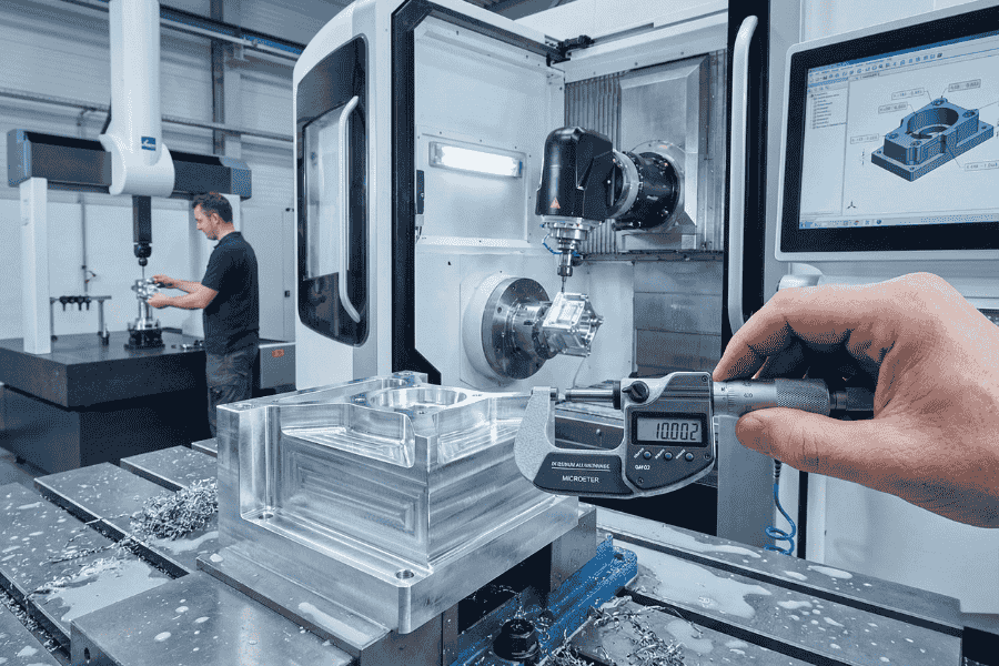
In the manufacturing world, there is no such thing as “perfect.” No matter how advanced the machine or how skilled the operator, it is physically impossible to manufacture a part to exact, absolute dimensions every single time. There will always be a microscopic degree of variation.
The job of the engineer is not to eliminate this variation but to control it. This is the definition of Machining Tolerances.
For our clients, understanding tolerances is the key to a successful project. Whether we are taking a raw Sand Casting and machining a precision bearing face, or milling a component from a solid billet of aluminium, the tolerances you specify on your drawing dictate the method of manufacture, the speed of production, and ultimately, the price you pay.
Specifying a tolerance that is too loose can lead to parts that do not fit together. However, specifying a tolerance that is tighter than necessary can triple your manufacturing costs without adding any functional value. This guide explores the standards, the costs, and the best practices for specifying machining tolerances in the UK.
The Quick Answer
Machining Tolerance is the allowable limit of variation in a physical dimension. It is typically expressed as a plus or minus range (e.g., ±0.05mm). If a shaft is designed at 10mm with a tolerance of ±0.05mm, any part measuring between 9.95mm and 10.05mm is acceptable. The tighter the tolerance (the smaller the number), the more precise the part must be. However, tighter tolerances require slower machining speeds, specialised tooling, and rigorous inspection, which significantly increases the cost. The “Golden Rule” is to apply tight tolerances to critical features where they are necessary for fit or function.
What Are Machining Tolerances?
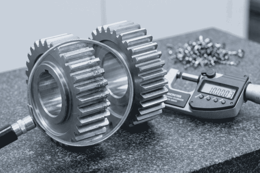
A tolerance is essentially a “margin of error” that you are willing to accept. In the UK, we almost exclusively work in metric measurements (millimetres).
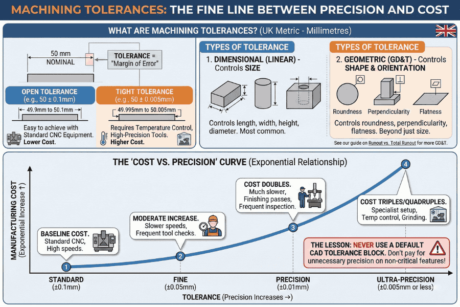
If you look at an engineering drawing, you will see a nominal dimension, for example, 50mm. If the drawing says 50 ± 0.1, it means the part can be anywhere from 49.9mm to 50.1mm. This is a relatively “open” tolerance that is easy to achieve with standard CNC equipment. If the drawing says 50 ± 0.005, the part must be between 49.995mm and 50.005mm. This is a “tight” tolerance that requires temperature-controlled machining and high-precision tools.
Types of Tolerance
1. Dimensional Tolerances (Linear) These control the size of a feature. This includes the length, width, height, or diameter of a hole. This is the most common type of tolerance seen on basic drawings.
2. Geometric Tolerances (GD&T) Sometimes, size isn’t enough. A hole might be the correct diameter, but is it perfectly round? Is it perpendicular to the base? Is the surface flat? Geometric Dimensioning and Tolerancing (GD&T) controls the shape and orientation of features. For a deeper dive into this, you can read our guide on the Difference Between Runout and Total Runout.
The “Cost vs. Precision” Curve
The most important concept for a buyer or design engineer to grasp is the exponential relationship between tolerance and cost.
Imagine a curve.
Standard Tolerances (±0.1mm): This is the baseline. Standard CNC machines can hit this all day long at high speeds. The cost is low.
Fine Tolerances (±0.05mm): The machinist needs to slow down slightly and check the tool wear more often. The cost increases moderately.
Precision Tolerances (±0.01mm): The machine must run much slower. We may need to take a “finishing pass” (cutting twice). The part must be inspected more frequently. The cost doubles.
Ultra-Precision (±0.005mm or less): This requires specialist setup, temperature control (as metal expands with heat), and perhaps grinding rather than milling. The cost can be 3 or 4 times higher than the standard part.
The Lesson: Never use a default tolerance block on your CAD software. If you set your default to ±0.01mm for every single dimension, you are essentially telling the machinist to treat the cosmetic edge of a bracket with the same care as a high-speed bearing journal. You are paying for precision that you do not need.
Standard Tolerances: ISO 2768
To save time, the industry uses a standard set of “General Tolerances.” Instead of writing ±0.1 on every single line of a drawing, engineers will state “General Tolerances to ISO 2768-m” in the title block.
ISO 2768 is the international standard for machined parts. It is broken down into four classes:
Fine (f): For precision metal components.
Medium (m): The industry standard for standard CNC machining.
Coarse (c): For rougher parts or general casting dimensions.
Very Coarse (v): Rarely used in precision engineering.
For most non-ferrous Precision CNC Machining jobs, ISO 2768-m (Medium) is the default. For example, under “Medium” class:
For dimensions between 6mm and 30mm, the tolerance is ±0.2mm.
For dimensions between 30mm and 120mm, the tolerance is ±0.3mm.
If a specific feature needs to be tighter than this, you add a particular tolerance to that dimension on the drawing. This tells the machinist exactly where to focus their effort.
The Foundry Factor: Casting vs. Machining Tolerances
At Castech, we are in a unique position because we often manage both the raw casting and the final machining. It is vital to understand that these two processes operate in different precision worlds.
Casting Tolerances
When we pour molten Aluminium or Bronze into a mould, the metal shrinks as it cools. This shrinkage is predictable, but not to the micron.
A raw sand casting might have a general tolerance of ±0.5mm to ±1.0mm.
A gravity die casting might be tighter, around ±0.3mm to ±0.5mm.
This is perfectly acceptable for the “as cast” surfaces, such as the body of a pump or the handle of a lever.
Machining Tolerances
However, where that casting mates with another part (e.g., bolt holes or a flange face), we need higher precision. We take the raw casting and machine those specific areas.
The machined features can be held to ±0.01mm or better.
The Hybrid Approach. The most cost-effective part is one that respects both processes. You should design the non-critical areas (like the outer skin) to looser casting tolerances, and only machine the critical areas (like the mating faces) to tight machining tolerances. This minimises the amount of metal removal required, saving time and waste.

Material Matters: Aluminium vs. Copper Alloys
The material you choose influences the tolerance we can hold.
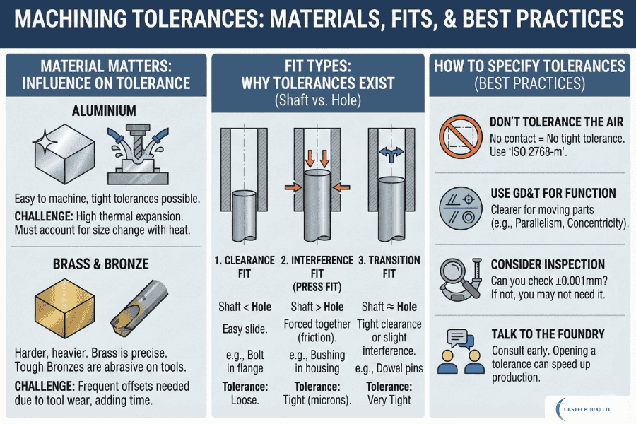
Aluminium: Aluminium is a machine dream. It is soft, cuts cleanly, and does not wear out tools quickly. We can hold very tight tolerances on Aluminium Castings. However, aluminium has a high coefficient of thermal expansion. If the part gets hot during machining, it expands. We have to account for this so that when it cools down, it is still within tolerance.
Brass and Bronze: These are harder and heavier. Free machining brass is excellent for precision, but tough Bronzes (like Aluminium Bronze) can be abrasive on tools. As the tool wears down, the dimensions of the part change. This means the machinist has to stop and adjust the machine (offsets) more frequently to maintain the tolerance, which can add time to the process.
Fit Types: Why Do We Need Tolerances?
Ultimately, tolerances exist to ensure parts fit together. In engineering, there are three main types of “fit” between a hole and a shaft.
1. Clearance Fit: The shaft is always smaller than the hole. The parts slide together easily.
Example: A bolt passing through a flange.
Tolerance: Relatively loose.
2. Interference Fit (Press Fit) The shaft is always slightly larger than the hole. The parts must be forced together using a press or by heating one and freezing the other. They stay stuck together by friction.
Example: A bushing pressed into a housing.
Tolerance: Extremely tight (often microns) to ensure the interference is consistent.
3. Transition Fit: The shaft and hole are almost the same size. Depending on where they fall in their tolerance range, it might be a tight clearance or a slight interference.
Example: Dowel pins used for precise alignment.
Tolerance: Very tight precision required.
How to Specify Tolerances Correctly (Best Practices)
To ensure you get the best quality parts, follow these rules of thumb:
Do not Tolerance the Air: If a surface does not touch anything else, it does not need a tight tolerance. Leave it as “ISO 2768-m” or standard casting tolerance.
Use GD&T for Function: Use geometric tolerances like Parallelism or Concentricity for moving parts. This is often clearer than just using dimensional plus/minus numbers.
Consider Inspection: If you ask for a tolerance of ±0.001mm, do you have the equipment to check it? If you cannot inspect it, you probably do not need it.
Talk to the Foundry: Before finalising your design, ask us. We can tell you, “If you open this tolerance by 0.05mm, we can make it 20% faster.”
Conclusion
Machining tolerances are the language of precision. They define the boundary between what is acceptable and what is scrap. But like any language, they must be used correctly to be effective.
By understanding the difference between general tolerances (for cost saving) and precision tolerances (for function), and by recognising the interplay between raw casting and final machining, you can optimise your designs.
At Castech, our engineers are experts in navigating this balance. We ensure that every Precision CNC Machining project we undertake meets the rigorous standards required for aerospace and defence, without adding unnecessary cost for our customers.